


What is LM3900 Quadruple Norton Operational Amplifier?
Introduction
The LM3900 consists of four independent dual-input internally compensated amplifiers. These amplifiers are specifically designed to operate on a single power supply voltage and provide a large output voltage swing. They utilize current mirrors to achieve in-phase input functionality.
Applications include AC amplifiers, RC active filters, low-frequency triangle waves, square wave, and pulse waveform generation circuits, tachometers, and low-speed, high-voltage digital logic gates.
Table of content
What is LM3900?
The operating temperature range for the LM3900 is 0°C to 70°C. These devices comprise four separate, highly gain, frequency-compensated Norton operational amplifiers, specifically made to run across a wide voltage range from a single supply. Split supply operation is also feasible. The low supply current drain is mostly unaffected by the supply voltage's magnitude. Large output voltage swings and a broad bandwidth are features of these devices.
LM3900 Op-Amp Pinout
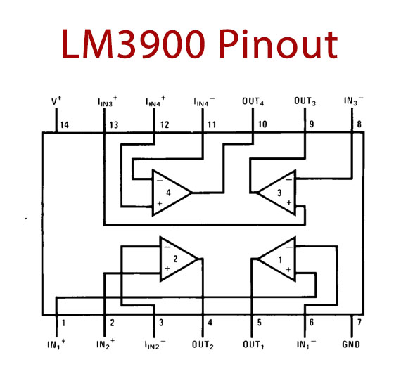
Figure1-LM3900 Op-Amp Pinout
LM2900 Op-Amp Pinout Configuration
|
Pin Number |
Pin Name |
Description |
|
1 |
1IN+ |
Non-Inverting Input 1 |
|
2 |
2IN+ |
Non-Inverting Input 2 |
|
3 |
2IN- |
Inverting Input 2 |
|
4 |
2OUT |
Output Pin 2 |
|
5 |
1OUT |
Output Pin 1 |
|
6 |
1IN- |
Inverting Input 1 |
|
7 |
GND |
Ground Pin |
|
8 |
3IN- |
Inverting Input 3 |
|
9 |
3OUT |
Output Pin 3 |
|
10 |
4OUT |
Output Pin 4 |
|
11 |
4IN- |
Inverting Input 4 |
|
12 |
4IN+ |
Non-Inverting Input 4 |
|
13 |
3IN+ |
Non-Inverting Input 3 |
|
14 |
VCC |
Positive Supply Voltage |
LM3900 Features & Specifications
- Wide Range of Supply Voltages, Single or Dual Supplies
- Wide Bandwidth
- Large Output Voltage Swing
- Output Short-Circuit Protection
- Internal Frequency Compensation
- Low Input Bias Current
- Designed to Be Interchangeable with National Semiconductor LM2900 and LM3900, Respectively
- Max Supply Voltage 36V
- Max Input Current 20mA
- Input bias current 200nA
- CMRR 70 dB
- Unity-gain bandwidth (inverting input) 2.5MHz
LM3900 Working Principle
1、LM3900 Symbol (per amplifier)
The LM3900 symbol (per amplifier) is shown below:
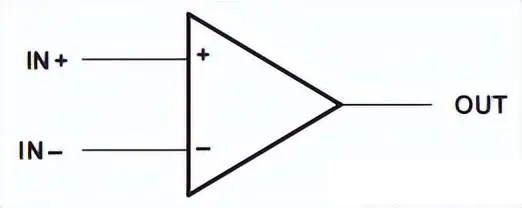
Figure2-LM3900 Symbol (per amplifier)
2、LM3900 Schematic (per amplifier)
The LM3900 schematic (per amplifier) is shown below:
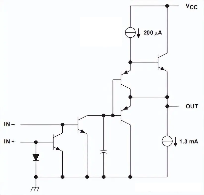
Figure3-LM3900 Schematic (per amplifier)
Where to use LM2900 Op-Amp?
The LM3900 is classified as a Quad Package Operational Amplifier since it has four independent Op-Amps.
The LM3900, as seen above, is packaged in a 14-pin DIP and features four identical op-amps. Each op-amp has an output as well as inverting and non-inverting inputs. These op-amps behave entirely differently from standard op-amps, though. The LM2900 reacts to a differential current, whereas the typical op-amp operates if there is a voltage difference at its inputs. This operational amplifier's input stage is designed to distinguish between different currents, rather than acting as a differential amplifier. With an overall gain of 70 dB, the current mirror at the non-inverting input can readily subtract the current at the inverting input from the current at the inverting input. The output saturates high when the inverting input is less than the value at the non-inverting input, and low when the inverting input is higher. The output's feedback to the inverting input works to minimize the difference in current, which is often very little. Thus, it may be concluded that voltage, rather than current, is used by this op-amp.
LM3900 Op Amp Circuit
LM3900 Norton amplifier circuit
Norton amplifiers have worse noise immunity compared to typical bipolar amplifiers. The circuit layout is more critical because coupling from the output to the non-inverting input can cause oscillation. Extra care is needed when driving either input from a low-impedance source. A current-limiting resistor should be connected in series with the input to limit the peak input current. Although the device will not be damaged by currents up to 20 mA, at higher current levels, especially at high operating temperatures, the current mirror at the non-inverting input will saturate and result in a loss of mirror gain.
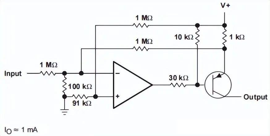
Figure4-Voltage-Controlled Current Source
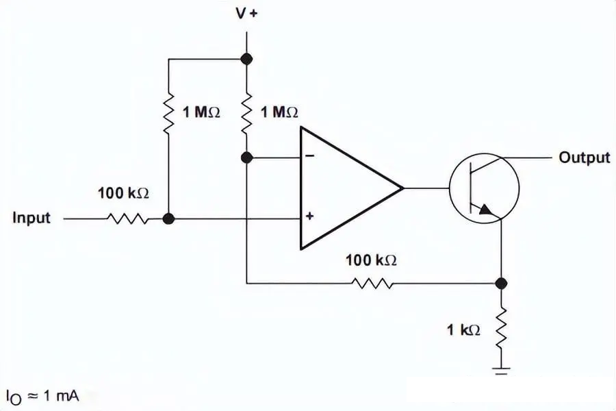
Figure5-Voltage Controlled Current Sink
Audio mixer circuit using LM3900
To use a single amplifier to amplify multiple audio inputs, we require an audio mixer. With a 14-pin dual inline packaging, it is a quadruple Norton operational amplifier. The audio mixer circuit that uses IC LM3900 is straightforward to construct. The LM3900 offers various power supply voltages (4.5v to 32v).
Since the LM3900 complies with internal frequency, four distinct audio inputs can be mixed and amplified. The single input gain to audio can be changed using the variable resistors VR1 through VR4. With a mixed audio output signal, the circuit only has a low gain; an additional amplifier can enhance the audio output.
Hardware Components
The following components are required to make an Audio Mixer Circuit
|
S.no |
Component |
Value |
Qty |
|
1. |
IC |
LM3900 |
4 |
|
2. |
Variable Resistor |
1K Ohms |
4 |
|
3. |
Resistor |
1M, 330 Ohms, 470 Ohms |
4, 5, 1 |
|
4. |
Capacitors |
0.1uF |
5 |
Audio Mixer Circuit
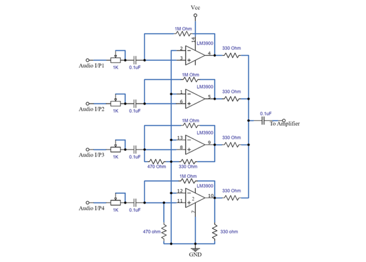
Figure6-Audio Mixer Circuit
Working Explanation
Building an audio mixing circuit requires an amplifier stage, which this circuit's LM3900 IC provides. Variable resistors (VR1 through VR4) regulate each audio input, making it simple to adjust each audio channel. All internal amplifiers amplify audio input signals.
Audio signals and non-inverting pins provide the means of inverting the amplifier's input. Every stage of the feedback setup process uses a 1M resistor. Lastly, the output signals are merged using an external power amplifier.
Each of the four internal LM3900 amplifiers operates independently with great gain compensation. It can run from a split supply and requires only one power source. There is a significant output voltage swing and a broad bandwidth. For that audio mixer, a regulated DC power source and an audio signal that can be supplied directly as input or after pre-amplification are needed. Provide the global average (GND) for every non-inverting input. We could use an adjustable sliding potentiometer rather than using variable resistors to make the circuit look more professional.
Applications
- Line Drivers
- Line Receivers
- Active Filters
- Preamplifiers
- Integrators
- Crossover Networks
- Unity-Gain Buffer
- Relaxation Oscillator
- Voltage regulator
- Current differentiator
2D Model and Dimensions
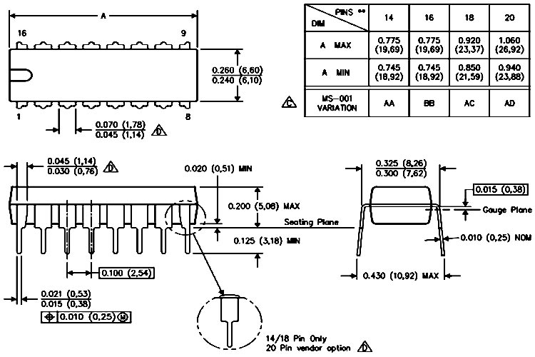
Figure7-2D Model and Dimensions
 DC-DC converter RFB-0505S: Specification,Datasheet,Features and Applications6/13/2024 425
The RFB-0505S is a DC-DC converter from RECOM Power, Inc., belonging to the RFB Series. It features a Single In-Line Package (SIP7) and provides a single unregulated output. This converter offers 1 watt of power with an output voltage of 5V and is rated for an isolation voltage of 1kV.
Read More > Understanding the RFMM-0505S DC-DC Converter: A Comprehensive Guide6/4/2024 605
In the world of electronics, ensuring efficient power management is crucial for the performance and reliability of devices. One of the key components in achieving this is the DC-DC converter. Today, we dive into the specifics of the RFMM-0505S DC-DC converter, exploring its features, applications, and benefits.
Read More > 12V DC-DC Converter AM2G-0512SZ: Specifications, Datasheet, Applications and Features6/3/2024 514
A DC-DC converter is an essential electronic device to convert a direct current (DC) source from one voltage level to another. These converters are widely employed in various applications, including portable electronic devices, automotive systems, and renewable energy installations.
Read More > Exploring the MMBT3906 Transistor: A Comprehensive Guide5/24/2024 734
The goal of the Taiwan Semiconductor MMBT3906 PNP Bipolar Transistor is to provide a high surge current capability with minimal power loss. This transistor is perfect for automated installation and has high efficiency.
Read More > What is 2N3904 Transistor? Pinout, features and application examples5/15/2024 879
The 2N3904 is an NPN transistor used for general-purpose switching or low-power amplification applications. It is primarily designed for medium voltage, and low power applications, and operates at moderate speed.
Read More >
SUPPORT
ABOUT BITFOIC
QUICK LINKS
Connect with us
Tel: 86-755-23606554
E-mail: [email protected]
Address: Room A29, 24 / F, Hoi Tak Wai, Prince Edward industrial building, 706 Prince Edward Road East, San Po Kong, Kowloon,Hongkong
Mon-Fri: 09.30 AM - 18.30 PM


