


The Best Guide to 2SC5200 Transistor
2SC5200 is a popular NPN Power transistor used in Audio frequency amplifiers and High power audio circuits. It is called a Power transistor due to its high Collector to Emitter breakdown voltage of 230V, the high collector current of 15A, and high current gain of 160.
Ⅰ 2SC5200 transistor Overview
The 2SC5200 transistor is an NPN-structure device with new BiT-LA technology. It is recommended for use in the output stages of VLF. It features high power dissipation (150W), high collector current (up to 15A), and edge frequency (up to 30MHz).
2SC5200 Transistor was originally manufactured by TOSHIBA in JAPAN and is now obsolete due to the development of a similar but cheaper TTC5200 Transistor. Some companies(except Toshiba) still manufacture 2SC5200 and you can easily find it on the internet.
Ⅱ 2SC5200 Pinout

Figure1-2sc5200 pinout
Ⅲ Pin Configuration
|
Pin Number |
Pin Name |
Description |
|
1 |
Base |
Controls the biasing of the transistor, Used to turn ON or OFF the transistor |
|
2 |
Collector |
Current flows in through the collector, normally connected to load |
|
3 |
Emitter |
Current Drains out through emitter, normally connected to ground |
Ⅳ 2SC5200 CAD Model
Symbol

Figure2-2SC5200 Symbol
Footprint

Figure3-2SC5200 Footprint
3D Model

Figure4-3D Model
Ⅴ Features
- High-power NPN Transistor
- DC Current Gain (hFE) 55 to 160
- Continuous Collector current (IC) is 15A
- Collector-Emitter voltage (VCE) is 230 V
- Collector-Base voltage (VCB) is 230V
- Emitter Base Voltage (VBE) is 5V
- The transition Frequency is 30MHz
- Available in To-264 Package
Ⅵ 2SC5200 Specs
The power dissipation rating of the 2SC5200 transistor is 150 watts which makes it suitable for AF amplifier circuits. Due to this high power usage, it is always used with a heatsink in a circuit.
Given below are the detailed specs of the 2SC5200 Transistor.
|
Characteristics |
Symbol |
Rating(Max.) |
|
Collector-base voltage |
VCBO |
230 V |
|
Collector-emitter voltage |
VCEO |
230 V |
|
Emitter-base voltage |
VEBO |
5 A |
|
Collector current |
IC |
15 A |
|
Base current |
IB |
1.5 A |
|
Collector output capacitance |
Cob |
200 pF |
|
DC current gain |
hFE |
160(VCE= 5V, IC= 1 A) |
|
Collector power dissipation |
PC |
150 W |
|
Junction temperature(TC = 25°C) |
Tj |
150 °C |
|
Operating temperature range |
Tstg |
−55 to 150 |
2SC5200 Specs Table
Ⅶ 2SC5200 Equivalent Transistor
Transistors that are exactly similar or equivalent to 2SC5200 and can be replaced with it are TTC5200, 2SC3320, 2SC5242, FJL4315 2SD1313, MJL3281A, and KTC5242.
Ⅷ PNP Complementary
PNP Complementary of 2SC5200 is 2SA1943
Ⅸ Where to use the 2SC5200 Transistor
The 2SC5200 is a high-power NPN transistor originally from Toshiba. Due to its high current gain and collector current, it is very commonly used in ‘High power audio circuits or AF amplifiers. But now the Transistor is absolutely from Toshiba and it has been replaced with TTA5200, but still the good old 2SA5200 can still be found in the market since it is still being cloned by other manufacturers in China.
Ⅹ How to use 2SC5200?
The 2SC5200 and its sibling, the 2SA1943, are mostly utilized in amplifier designs. Most amplifiers use a push-pull circuit resembling a Class B amplifier, which necessitates the use of both NPN and PNP transistors. The 2SA1943 is a PNP transistor, while the 2SE5200, an NPN transistor, is its complementary device. High-power amplifiers frequently combine the use of both of these transistors.
Transistors are always used in conjunction with a heat sink since they tend to heat up quickly due to their high switching frequency and high collector current. The heat sink should be isolated from the rest of the circuit because it will double as the transistor's collector pin.
These transistors, which can respond to frequencies between 5Hz and 100kHz and have a very good sensitivity of 0.75Vrms, are frequently employed to create stereo systems with a power rating of 200W or higher. It is perfect for audio applications since it has a very low signal-to-noise ratio and minimal overall harmonic distortion.
Ⅺ Applications
2SC5200 is commonly used to build stereo systems, which have a power rating of 200W or greater. These transistors can respond to frequencies from 5Hz-100kHz with a very high sensitivity of 0.75Vrms and have less total harmonic distortion making them ideal for audio applications.
- Audio frequency Amplifier
- AF /RF circuits
- Low Slew rate devices
- Push-Pull configuration circuits
- high current switching (upto 15A) loads
- Can be used as medium Power switches
Ⅻ 2SC5200 Package
Dimensions of 2SC5200 in TO-3P(L) package
2D dimensions will help you in placing this component at the time of making the circuit on a perf board or a PCB.

Figure5-2D-Model
Dimensions of 2SC5200 in TO-264 package

Figure5-Dimensions of 2SC5200 in TO-264 package
XIII 2sc5200 vs ttc5200 vs 2n3055 vs 2n3773
The specification comparison of transistors will really help in the replacement process.
|
Characteristics |
2sc5200 |
2n3055 |
Ttc5200 |
2n3773 |
|
Collector to base voltage (VCB) |
230V |
100V |
230V |
160V |
|
Collector to emitter voltage (VCE) |
230V |
60V |
230V |
140V |
|
Emitter to base voltage (VEB) |
5V |
7V |
5V |
7V |
|
Collector current (IC) |
15A |
15A |
15A |
16A |
|
Power dissipation |
150W |
115W |
150W |
150W |
|
Junction temperature (TJ) |
150°C |
200°C |
150°C |
200°C |
|
Transition frequency (FT) |
30MHZ |
2.5MHZ |
30MHZ |
- |
|
Gain (hFE) |
35 to 160hFE |
35 to 160hFE |
35 to 160hFE |
5 to 60Hfe |
|
Package |
TO-264 |
TO-3 |
TO-264 |
TO-3 |
XIII 2sc5200 inverter circuit

Figure6-2sc5200 inverter circuit
The 2SC5200 inverter circuit is seen in miniature in the image. It comprises two 2SC5200 transistors, a step-up transformer, and a battery. The power switching function of the 2SC5200 transistor converts the DC signal to AC when it reaches the two transistor networks. However, the voltage level is insufficient for supply, so the step-up transformer raises the voltage level to 230v.
XIV How to Safely Long Run in a Circuit
Use it at least 20% below its maximum ratings for long-lasting performance, as we always advise. Drive no more than 12A of load, as the transistor's maximum collector current is 15A, and no more than 180V of load, as the transistor's maximum collector-to-emitter voltage is 230V. Given that it is a high-power transistor with a heatsink connection, it is essential to use a suitable heatsink. It is crucial to take care that the heatsink does not come into contact with any circuit connections because the transistor's collector is also connected to the heatsink connection.
The minimum to maximum storage and operating temperature of the transistor ranges from -55 degrees centigrade to +150 degrees centigrade. For good and long-term performance of the transistor, the temperature around the transistor should not touch these minimum and maximum limits.
XV 2sc5200 Datasheet
 DC-DC converter RFB-0505S: Specification,Datasheet,Features and Applications6/13/2024 411
The RFB-0505S is a DC-DC converter from RECOM Power, Inc., belonging to the RFB Series. It features a Single In-Line Package (SIP7) and provides a single unregulated output. This converter offers 1 watt of power with an output voltage of 5V and is rated for an isolation voltage of 1kV.
Read More > Understanding the RFMM-0505S DC-DC Converter: A Comprehensive Guide6/4/2024 582
In the world of electronics, ensuring efficient power management is crucial for the performance and reliability of devices. One of the key components in achieving this is the DC-DC converter. Today, we dive into the specifics of the RFMM-0505S DC-DC converter, exploring its features, applications, and benefits.
Read More > 12V DC-DC Converter AM2G-0512SZ: Specifications, Datasheet, Applications and Features6/3/2024 499
A DC-DC converter is an essential electronic device to convert a direct current (DC) source from one voltage level to another. These converters are widely employed in various applications, including portable electronic devices, automotive systems, and renewable energy installations.
Read More > What is LM3900 Quadruple Norton Operational Amplifier?5/30/2024 1059
The LM3900 consists of four independent dual-input internally compensated amplifiers. These amplifiers are specifically designed to operate on a single power supply voltage and provide a large output voltage swing. They utilize current mirrors to achieve in-phase input functionality. Applications include AC amplifiers, RC active filters, low-frequency triangle waves, square wave, and pulse waveform generation circuits, tachometers, and low-speed, high-voltage digital logic gates.
Read More >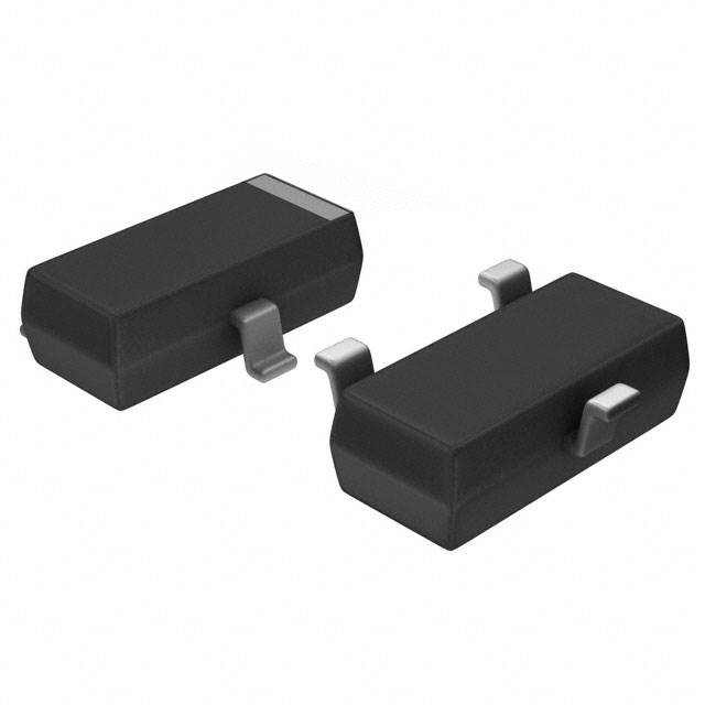 Exploring the MMBT3906 Transistor: A Comprehensive Guide5/24/2024 714
The goal of the Taiwan Semiconductor MMBT3906 PNP Bipolar Transistor is to provide a high surge current capability with minimal power loss. This transistor is perfect for automated installation and has high efficiency.
Read More >
SUPPORT
ABOUT BITFOIC
QUICK LINKS
Connect with us
Tel: 86-755-23606554
E-mail: [email protected]
Address: Room A29, 24 / F, Hoi Tak Wai, Prince Edward industrial building, 706 Prince Edward Road East, San Po Kong, Kowloon,Hongkong
Mon-Fri: 09.30 AM - 18.30 PM


